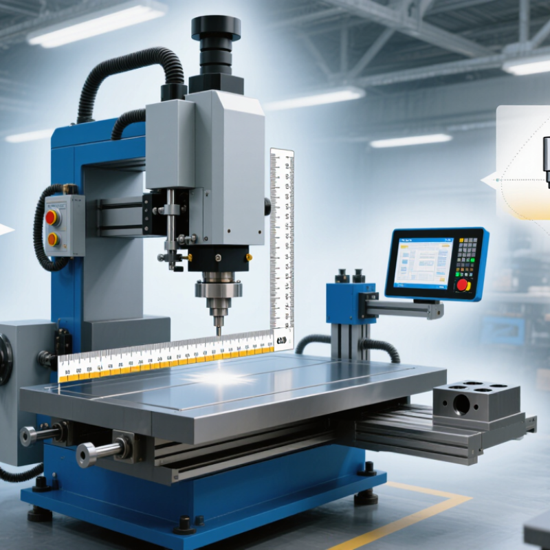
| Machine Type | Hydraulic die spotting machine; servo-hydraulic machine; mechanical or toggle-assisted design | Hydraulic or servo-hydraulic systems are generally suitable for mold assembly, trial fitting, repair, and low-speed die validation. | Different drive systems affect control, positioning, energy use, maintenance, and the ability to handle variable loads. | Confirm whether the machine supports controlled opening, closing, tilting, low-speed movement, pressure holding, and safe mold access. |
| Required Clamping Force | Common machine classes range from approximately 500 kN to more than 10,000 kN; select according to die mass, projected load, and safety margin. | Smaller machines for precision molds and compact dies; higher-force machines for large automotive, casting, or multi-cavity tooling. | Insufficient force can cause unstable mold handling, while excessive capacity can increase purchase price, floor loading, and energy consumption. | Calculate the maximum mold weight and required closing force from actual tooling data. Do not select only by nominal force. |
| Maximum Mold Dimensions | Typical working areas may range from about 400 × 400 mm to over 2,000 × 1,500 mm, depending on machine class. | Choose a working area larger than the maximum die footprint while preserving access for clamps, ejectors, sensors, and maintenance. | The mold must sit fully on the spotting table without overhang that could affect stability or access. | Check maximum mold length, width, height, mounting pattern, T-slots, clamping points, and allowable overhang. |
| Maximum Mold Weight | Typical rated capacities range from approximately 1,000 kg to more than 20,000 kg. | Select a capacity comfortably above the heaviest complete die, including inserts, adapters, lifting fixtures, and temporary tooling. | Rated capacity is normally based on structural and hydraulic limits; uneven loading may reduce the practical safe capacity. | Ask for the permitted load distribution, center-of-gravity limits, table deflection data, and lifting or loading procedure. |
| Opening Stroke | Common opening strokes are approximately 500–1,500 mm; larger machines may provide more. | Use a longer stroke for deep molds, tall inserts, core-pull mechanisms, and applications requiring clear access to parting surfaces. | Insufficient stroke can prevent full inspection or make insert installation difficult. | Measure the required daylight between mold halves, including ejector travel, lifting tools, and operator access clearance. |
| Daylight Between Platens | Typical maximum daylight may range from approximately 800 mm to 2,500 mm, depending on machine design. | Important for tall dies, stacked components, large inserts, and manual or robotic mold servicing. | Daylight determines whether the assembled mold can be loaded, opened, inspected, and removed safely. | Verify minimum and maximum mold height, open-position clearance, and whether daylight changes when the table is tilted. |
| Table Tilting Capability | Common options include no tilt, one-axis tilt, or two-axis tilt; typical tilt angles are approximately 90° in one axis or up to 180° in rotating designs. | Tilting is valuable for die inspection, polishing, insert replacement, spotting blue checks, and maintenance access. | Tilting can reduce manual handling and improve visibility of parting lines and difficult-to-reach areas. | Check tilt angle, rotation speed, locking method, allowable tilted load, center-of-gravity limits, and pinch-point protection. |
| Positioning Accuracy | Typical controlled positioning accuracy may be specified from approximately ±0.05 mm to ±0.20 mm, depending on machine size and measurement method. | Use higher accuracy for precision injection molds, die-casting dies, progressive dies, and tooling with tight parting-line requirements. | Accurate positioning supports repeatable spotting and reduces rework during mold fitting. | Request measured repeatability, not only nominal resolution. Confirm test conditions, measurement points, and calibration method. |
| Operating Speed | Fast approach speeds may be several hundred millimeters per second, while spotting and final closing should use controlled low speed. | High approach speed improves productivity; precise low-speed movement is essential near parting surfaces and inserts. | A machine needs both productivity and fine control; maximum speed alone is not a useful quality indicator. | Compare approach speed, spotting speed, crawl speed, acceleration control, stopping distance, and speed under load. |
| Pressure and Force Control | Adjustable hydraulic pressure, proportional valves, force monitoring, and programmable pressure stages are common options. | Useful for controlled contact, protecting delicate inserts, checking flash areas, and repeatable die fitting. | Controlled force prevents unnecessary damage when the die halves or inserts are not fully aligned. | Verify force-control resolution, pressure stability, alarm limits, data logging, and automatic overload protection. |
| Control System | Basic manual controls; touchscreen PLC control; programmable recipes with position, speed, pressure, and sequence monitoring. | Manual control suits occasional repair work; programmable control is better for repeated tooling trials and standardized processes. | Recipe storage improves repeatability between operators and reduces setup errors. | Check user permissions, recipe backup, multilingual support, diagnostic functions, HMI visibility, and control-system service life. |
| Table and Platen Design | Hardened or machined steel surfaces; T-slots, threaded holes, clamping rails, replaceable wear plates, and optional adapter plates. | Choose the interface that matches existing mold bases, clamps, lifting devices, and workshop fixtures. | A suitable table interface reduces setup time and prevents unsafe improvised clamping. | Confirm table flatness, allowable surface pressure, slot dimensions, hole pattern, replaceability, and corrosion protection. |
| Loading and Handling | Overhead-crane loading; integrated loading table; powered roller or sliding system; robotic or semi-automatic handling. | Integrated handling is useful for heavy dies or frequent changeovers; crane loading may be sufficient for low utilization. | Handling arrangements affect installation time, labor requirements, and the risk of impact damage. | Confirm loading height, transfer path, crane capacity, floor clearance, lifting points, and compatibility with existing equipment. |
| Safety Features | Guarding, interlocked doors, emergency stops, two-hand controls, light curtains, anti-drop protection, overload monitoring, and safety-rated control circuits. | All applications require a documented risk assessment and safeguards appropriate to movement, crushing, tilting, and stored hydraulic energy. | Die spotting involves heavy moving components and pinch points; safety must not depend only on operator awareness. | Verify conformity with applicable local machinery-safety legislation, safety validation documents, lockout provisions, and operator training requirements. |
| Energy Consumption | Variable-displacement or servo-hydraulic pumps generally reduce idle energy compared with fixed-speed systems, but actual consumption depends on cycle and load. | Energy-efficient systems are beneficial for frequent operation, long idle periods, or facilities with energy-management targets. | Hydraulic power demand varies significantly between approach, spotting, holding, and tilting operations. | Request measured power data for a representative cycle rather than relying only on installed motor power. |
| Maintenance Requirements | Hydraulic oil and filter service; lubrication; seal and hose inspection; alignment checks; electrical and safety-system testing. | Choose accessible service points and commonly available components when uptime is critical. | Maintenance access and spare-parts availability directly affect total cost of ownership. | Review maintenance intervals, oil specifications, filtration grade, recommended spare parts, service response, and documentation. |
| Installation Conditions | Requirements may include reinforced foundations, level flooring, electrical supply, hydraulic-fluid handling, ventilation, and overhead clearance. | Large machines may require a foundation design and lifting plan before delivery. | Insufficient foundation strength or floor flatness can affect alignment, vibration, and long-term accuracy. | Obtain total machine weight, floor-loading data, anchor layout, power requirements, transport dimensions, and commissioning requirements. |
| Application Match | Injection molds; die-casting dies; stamping dies; progressive dies; compression molds; maintenance and repair tooling. | Select based on the dominant tooling type and the most demanding mold dimensions, weight, access, and accuracy requirements. | A machine optimized for small precision molds may not be suitable for large automotive dies or high-load casting tooling. | Run a sample-die trial using representative tooling and document loading, opening, tilting, spotting, and removal steps. |
| Total Cost of Ownership | Purchase price plus installation, foundation work, tooling adapters, energy, maintenance, calibration, training, and downtime. | Compare lifecycle cost over the expected service period rather than comparing the initial price alone. | The lowest initial price may result in higher operating cost, longer setup time, or limited future capacity. | Request a complete quotation including options, commissioning, warranty, training, spare parts, software, and service terms. |