o
p
t
i
m
a
r
o
b
o
t
i
c
s

Make a Call


Make a Call
Blogs
How to Buy Free Standing Giant LED Letters in 2026?
Buying free standing giant led letters in 2026 requires more than choosing the brightest display. You need a safe, durable, and visually consistent installation.
David Hickey, a respected sign-industry professional, has described signage as “a silent salesperson.” That idea matters here. Your letters should attract attention, communicate clearly, and support the event’s atmosphere without overwhelming it.
Start with the venue. Measure doorways, elevators, stage access, and the final display area. A 1.5-meter letter may look impressive online but become difficult to transport. Check the letter depth, base stability, cable placement, and total weight before ordering.
Then examine construction quality. Aluminum frames, protected LED modules, sealed wiring, and weighted bases usually offer better long-term reliability. Ask whether the lighting is dimmable. Bright white LEDs can appear harsh in photographs, especially against glossy floors. Warm white, RGB, or adjustable color options may create a more controlled effect.
Safety comes first.
Request certification details, power requirements, warranty coverage, and replacement-part availability. Outdoor use also requires suitable weather protection, but product labels can be unclear. Ask for the actual IP rating and operating limits.
A supplier’s photos are useful, but they are not proof of performance. Request recent installation videos, close-up images, and customer references. I would also inspect one sample letter whenever possible. Small defects become obvious when several letters stand together.
Price remains important, yet the cheapest option may bring unstable bases, uneven brightness, or slow repairs. This guide explains how to compare free standing giant LED letters carefully, realistically, and with room for better judgment.
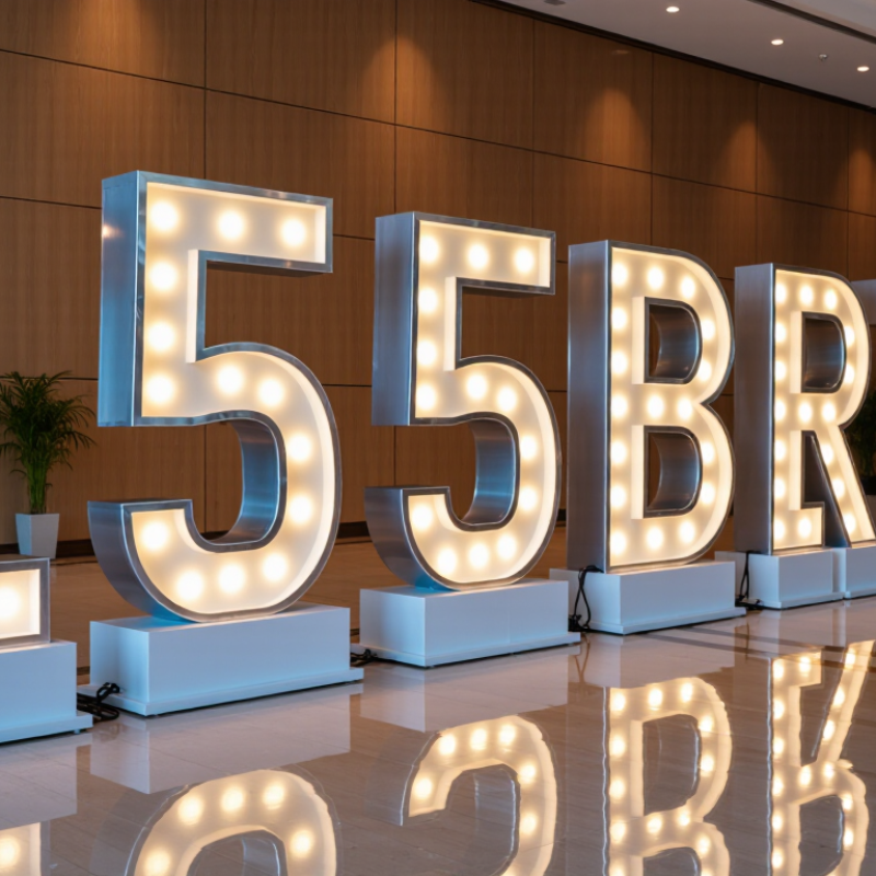
Table of Contents [Hide]
What Free-Standing Giant LED Letters Are and How They Work
How to Buy Free Standing Giant LED Letters in 2026?
Free-standing giant LED letters are oversized illuminated signs that stand independently on a floor, platform, or weighted base. Each letter usually contains LED modules, wiring, a power supply, and a controller. When connected, these parts create steady light, chasing effects, or color changes. Unlike backlit acrylic letters, LED letters can produce stronger visual impact from several viewing angles. Their structure also demands careful attention to stability, cable routing, and weather protection.
Energy use matters during long events. The U.S. Department of Energy reports that LED lighting uses at least 75% less energy than incandescent lighting and can last up to 25 times longer. Still, brightness claims may not match real conditions. Direct sunlight, frosted covers, and uneven LED spacing can reduce perceived intensity. Ask for measured power consumption, lumen information, operating temperature, and a short video of the exact letter style. A professional supplier should also explain installation weight and maintenance access.
Tips: Check the base width before ordering. Measure doorways, elevators, and storage areas. Choose low-voltage systems with protected connectors and certified power supplies. Request a sample letter first. It may reveal uneven lighting. Leave space behind each letter for airflow and cable access. For outdoor use, confirm the enclosure rating and anchoring method. Never assume a heavier letter is automatically safer; poor weight distribution can still cause tipping. Forecast the full cost, including delivery, setup, cleaning, and replacement modules.
Brands
Proudly Trusted by Top Suppliers Worldwide







Let us know and we will automate, together to fit your industrial needs.
 +91-97254 16844
Clients
Proudly Trusted by Top Companies Worldwide


Do you need Help? Get in touch.
X
Please fill out the form below and we will get back to you as soon as possible.