o p t i m a r o b o t i c s

Blogs

How to Choose the Best CVBS Camera Module for Your Project?

Choosing the best Cvbs Camera Module begins with the scene, not the product label. A bright warehouse, a dim vehicle cabin, and a roadside camera demand different imaging choices. Lens angle, sensor size, resolution, signal stability, and night performance can change the final result dramatically. A module that looks sharp on a supplier’s chart may produce soft edges on a real monitor.

Imaging expert Dr. Albert Theuwissen offers a useful principle: “The image sensor is the heart of a camera.” That idea matters when comparing a Cvbs Camera Module. Sensor quality affects color, motion clarity, noise, and detail under uneven lighting. However, the sensor is not the whole system. The lens, infrared response, housing, cable length, and video output circuit also deserve practical testing.

Check the module with your intended display and recorder. Test it beside a window, under weak indoor light, and during fast movement. Watch for rolling noise, washed highlights, unstable color, and delayed signal output. Small flaws become expensive after installation.

Compatibility is easy to overlook. Confirm the CVBS format, power voltage, connector type, mounting dimensions, and operating temperature. Ask for sample footage, not only specifications. Suppliers may present ideal conditions. Your project will not.

There is no perfect module. That is the uncomfortable part. The right choice balances image quality, reliability, available space, service life, and budget. A careful field test often reveals more than a polished datasheet.
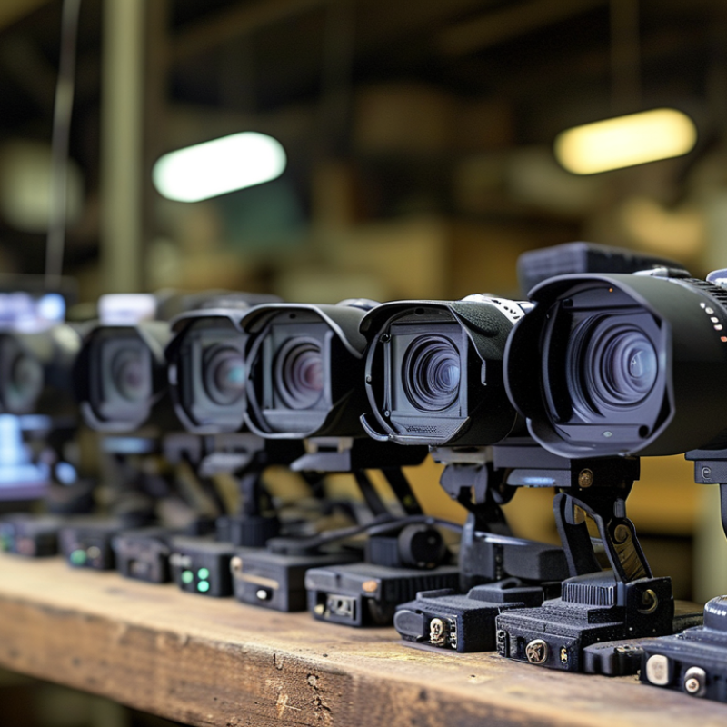
How to Choose the Best CVBS Camera Module for Your Project?

Understanding CVBS Camera Modules and Their Core Features

How to Choose the Best CVBS Camera Module for Your Project?

A CVBS camera module converts light into an analog composite video signal. It usually sends video through one coaxial connection. This design remains useful for monitors, vehicle displays, inspection tools, and older control systems. Its core features include sensor size, video standard, lens angle, output format, and power requirements. Check whether the system uses NTSC or PAL. A mismatch may produce unstable images, rolling lines, or no picture. Test the module with the actual display, not only a product sheet. Specifications can look precise. Real installations are less forgiving.

Resolution matters, but lighting often matters more. A wide lens captures more space, yet it may make distant objects appear smaller. For a narrow cabinet, a compact lens can reduce unwanted edges. In a dim hallway, ask about low-light sensitivity and infrared support. Strong backlighting also requires practical exposure control.

Image quality depends on the scene. Not just pixels.

Power stability deserves careful attention. Confirm the module’s voltage range and current demand before wiring it. A long cable can introduce noise, especially near motors or switching equipment. During testing, inspect the image with the cable length used in the final project. I once approved a clear bench sample that developed faint horizontal interference after installation. That mistake changed my process. I now test vibration, temperature, lighting shifts, and connector fit before choosing a CVBS camera module. The overlooked detail may become the expensive one.

Defining Your Project’s Image, Format, and Environmental Requirements

Choosing a CVBS camera module starts with the image your project must produce. Define the scene before comparing specifications. Indoor monitoring may need balanced color and low noise. Outdoor equipment may need strong highlights, backlight control, and stable night performance. The ITU-R BT.601 standard specifies 720×480 and 720×576 active video samples for common digital representations of legacy television formats. Match the module’s output to your display, recorder, and cable system. A mismatch can create cropped images, unstable synchronization, or soft details.

Environmental requirements deserve equal attention. Check operating temperature, humidity, vibration, and cable length under real installation conditions. IEC 60529 defines IP protection levels, but an IP rating does not guarantee optical performance. Condensation can blur a lens, even when the enclosure remains sealed. In field testing, I have seen a camera pass bench tests and fail after repeated temperature changes. That result is uncomfortable, but useful. Test the complete module, lens, connector, and housing together.

Tips: Record a moving subject in bright sunlight and near darkness. Inspect rolling bars, color shifts, and edge distortion. Ask for measured sensitivity, signal-to-noise ratio, and synchronization tolerance, not only “high definition” claims. Confirm whether PAL or NTSC timing is required. The Consumer Technology Association’s video measurement guidance also emphasizes testing under defined lighting conditions, because isolated laboratory figures can mislead. Leave some margin for aging, cable loss, and imperfect installation.

How to Choose the Best CVBS Camera Module for Your Project? — Defining Your Project’s Image, Format, and Environmental Requirements

Evaluation Dimension Project Requirement Common Technical Options Selection Guidance Recommended Check
Video Standard Match the camera output with the display, recorder, or video processor. NTSC PAL Use NTSC where the system is designed for approximately 29.97 frames per second and 60 Hz video timing. Use PAL where the system requires approximately 25 frames per second and 50 Hz video timing. Confirm system compatibility
Output Interface Transmit a standard analog composite video signal over the intended cable length. Composite video output through a single-ended analog connection; typically carried through a 75-ohm video path. Choose a CVBS module when the project already uses analog monitors, DVRs, vehicle displays, inspection equipment, or legacy video equipment. Keep cable impedance and connector quality consistent. Verify connector and cable type
Image Resolution Balance recognizable detail with compatibility and processing limitations. Standard-definition CVBS output commonly supports about 480 visible lines in NTSC systems or about 576 visible lines in PAL systems. Effective detail depends on the sensor, lens, signal processing, and display. For general monitoring, select a module whose effective horizontal detail is appropriate for the display and recorder. Higher sensor pixel count does not automatically produce higher CVBS detail. Test the complete video chain
Frame Timing Prevent flicker, frame instability, or incompatibility with the host system. NTSC: approximately 29.97 fps
PAL: approximately 25 fps
Use the same video timing standard throughout the camera, monitor, capture device, and recorder. Avoid mixing standards unless the system includes a suitable converter. Check display and recorder settings
Lens Field of View Cover the required scene without excessive distortion or blind areas. Narrow view: approximately 30°–60° diagonal
Standard view: approximately 60°–90° diagonal
Wide view: approximately 90°–140° diagonal
Use a narrower lens for distant subjects and identification. Use a wider lens for rooms, dashboards, or nearby scenes. Very wide lenses can increase barrel distortion at the image edges. Measure distance and coverage area
Lens Mount and Focus Maintain a stable focus at the required working distance. Fixed-focus lens
Manual-focus lens
Board-mount lens
Fixed focus is suitable for stable, predefined distances. Manual focus is useful when the installation distance may change. Confirm the lens format, thread type, image circle, and sensor compatibility. Focus at installation distance
Day/Night Performance Produce usable images under changing illumination. Daylight color imaging
Automatic exposure control
Infrared-sensitive imaging
Mechanical or electronic day/night switching
For outdoor or low-light scenes, select a module with suitable automatic exposure behavior and infrared response. Confirm whether infrared illumination is supplied by the system or must be added separately. Test in both bright and dark conditions
Minimum Illumination Maintain acceptable image brightness in the lowest expected light level. Typical module specifications may range from below 0.1 lux for low-light designs to around 1 lux or higher for basic color imaging, depending on measurement conditions. Treat lux values as reference figures rather than direct performance guarantees. Ask how the value was measured, whether infrared lighting was used, and what signal-to-noise level was accepted. Evaluate real scene samples
Dynamic Range and Backlight Preserve useful detail when bright and dark areas appear together. Automatic gain control
Backlight compensation
Highlight control
Wide-dynamic-range processing
Prioritize backlight and dynamic-range functions for entrances, windows, roads, vehicle cabins, and scenes with strong sunlight. Check for motion artifacts in fast-changing scenes. Test against bright backgrounds
Color Reproduction Identify objects accurately under the project’s lighting conditions. Automatic white balance
Fixed white-balance presets
Manual white-balance adjustment
Automatic white balance is practical for changing environments. Manual or preset control can be preferable when lighting is fixed and consistent, such as machine vision assistance or enclosed equipment. Check under actual lighting
Power Supply Provide stable power within the module’s specified operating range. Common camera-module inputs include regulated low-voltage DC supplies such as 5 V, 9 V, or 12 V, depending on the design. Do not assume that similarly sized modules use the same voltage. Confirm input tolerance, current consumption, polarity, startup current, and protection requirements before connecting the module. Verify voltage and polarity
Power Consumption Fit the available power budget, battery capacity, and thermal design. Compact CVBS modules commonly consume from a fraction of a watt to several watts, depending on sensor operation, image processing, infrared switching, and heater functions. Calculate consumption for normal operation and the highest-load condition. Include external infrared lights, heaters, converters, and cable losses in the total system budget. Measure worst-case current
Operating Temperature Remain stable across the expected installation temperature range. Indoor designs may be suitable for approximately 0°C to 50°C. Industrial or outdoor designs may support wider ranges such as approximately −20°C to 60°C or beyond, subject to the specification. Select a temperature rating wider than the expected ambient range. Consider heat generated inside an enclosure, direct sunlight, cold startup, condensation, and thermal expansion. Include enclosure temperature rise
Ingress Protection Protect the module from dust, water, condensation, or cleaning procedures. No formal rating for open-board modules
Enclosed designs may use ratings such as IP54, IP65, or IP67 when properly manufactured and sealed
Use an appropriately sealed enclosure for outdoor, wash-down, dusty, or humid locations. The protection level applies to the complete assembled product, not automatically to the bare camera board. Assess the complete assembly
Mechanical Size Fit the camera into the available housing, bracket, or embedded device. Board dimensions may range from very compact embedded formats to larger modules with separate lens holders, connectors, or shielding. Reserve space for the lens, connector, cable bend radius, mounting holes, ventilation, and service access. Confirm optical center height and lens protrusion, not only board length and width. Create a mechanical drawing
Vibration and Shock Maintain focus and electrical connection in moving or mechanically active equipment. Standard embedded mounting
Reinforced mounting
Lockable or fixed-focus lens assembly
For vehicles, machinery, and mobile equipment, select a mechanically secure lens and connector arrangement. Use strain relief and test the assembled camera rather than the board alone. Perform vibration testing
Cable and Signal Distance Transmit a clean composite signal without visible noise or loss of detail. Short internal cable runs
Shielded coaxial cable
Differential or converted transmission for longer runs
For longer cable paths, use suitable shielded cable, correct termination, and a compatible distribution or conversion method. Ground loops and electromagnetic interference can cause rolling bars, hum, or image noise. Test final cable length
Integration Controls Configure image behavior after installation. Fixed factory settings
On-board adjustment controls
External configuration interface
Choose accessible controls for projects that require field adjustment. For sealed products, configure exposure, white balance, mirror function, and day/night behavior before final assembly. Document final settings
Validation Before Purchase Confirm that the selected module performs as expected in the complete product. Sample evaluation
Lighting test
Temperature test
Cable and interference test
Mechanical fit test
Evaluate the camera with the actual display, recorder, power supply, lens, enclosure, cable, and lighting conditions. A sample test is more reliable than comparing specifications alone. Approve a complete-system sample
Practical selection rule: Start by matching the NTSC or PAL format and the CVBS interface, then verify lens coverage, low-light performance, power input, temperature range, enclosure protection, and complete-system compatibility with a physical sample.

Comparing Lens, Resolution, Signal, and Power Specifications

How to Choose the Best CVBS Camera Module for Your Project?

Choosing a CVBS camera module starts with the lens, not the sensor. A 2.8 mm lens gives a wider view, while a 6 mm lens captures distant details. Measure the working distance before selecting focal length. A wide lens can make faces appear small. That mistake is easy to miss during bench testing.

Resolution also needs realistic expectations. ITU-R BT.470-6 defines traditional composite television formats, including 525-line and 625-line systems. A CVBS output cannot deliver modern digital sharpness, even with a high-pixel sensor. Check the active image area, TV lines, and low-light performance together. Signal compatibility matters too. Confirm NTSC or PAL timing, termination, connector type, and cable length. Poor impedance matching can create ghosting, ripples, or unstable images.

Power specifications deserve equal attention. Many compact modules use 5 V, but current demand can rise sharply when infrared lighting or image processing is enabled. Measure startup current, not only the typical value. A small voltage drop can produce random resets.

Tips:
Test the module through the actual cable and display. Record images at noon and in dim indoor light. Compare skin tones, edge detail, and motion blur. Industry testing guidance from EBU technical reports supports evaluating cameras under controlled lighting and repeatable conditions. My own practical warning is simple: datasheets often show ideal results. Your installation will not be ideal. Check heat, cable routing, and power noise before approving the design.

Evaluating Compatibility, Reliability, Installation, and Total Cost

How to Choose the Best CVBS Camera Module for Your Project?

Compatibility should be checked before image quality. Confirm the CVBS format, such as PAL or NTSC, with the monitor or recorder. Match the module’s output connector and use 75-ohm coaxial cable where required. A 12V camera may still fail if the power supply creates voltage drops. Check the lens angle, mounting holes, and available space. A wide lens can hide corners, but it may also distort nearby objects.

Reliability depends on more than a sealed housing. Review operating temperature, vibration resistance, moisture protection, and connector strength. In field installations, heat near a metal panel can soften weak cables. Test the camera during cold starts and long operating periods. I once overlooked a loose connector, and the intermittent image looked like a sensor fault. That mistake delayed installation. Test early.

Installation effort affects the real cost. Measure cable routes before ordering, and allow space for service access. A low-priced module can become expensive after adapters, brackets, replacement cables, and labor are added. Estimate power consumption and spare units too. Check whether replacement modules preserve the same wiring and image settings. A small difference can require rewiring. Keep records of test results, connector types, and failure conditions. That evidence supports dependable purchasing decisions.

Selecting and Verifying the Best CVBS Camera Module for Your Application

How to Choose the Best CVBS Camera Module for Your Project?

Selecting a CVBS camera module starts with the application, not the advertised resolution. Define the scene, viewing distance, lighting, and available mounting space. For moving equipment, test image stability during vibration and sudden direction changes. Confirm the video standard, such as PAL or NTSC, before ordering. A small mismatch can stop the system from displaying correctly. I have seen a clear camera fail because its connector and signal format were overlooked.

Verification should happen with the complete system. Connect the module to the intended display or recorder using the planned cable length. Check color accuracy, edge detail, motion blur, and image noise under daylight and low light. Use a waveform monitor or oscilloscope when possible to inspect the composite signal and termination. Test the camera during startup, temperature changes, and extended operation. Record actual results, not only supplier specifications. A datasheet is useful, but limited.

Inspect the lens angle carefully. A wide lens may capture more space but can distort nearby objects. Confirm supply voltage, current consumption, connector layout, and operating temperature. Request a sample before placing a larger order. Run it beside the final enclosure, lighting, and cable assembly. I once accepted a module after a short indoor test, then found poor night detail outdoors. That mistake changed my evaluation checklist. Reliable selection comes from repeatable tests, clear records, and honest attention to weak points.

Brands

Proudly Trusted by Top Suppliers Worldwide

Let us know and we will automate, together to fit your industrial needs.

Clients

Proudly Trusted by Top Companies Worldwide

Do you need Help? Get in touch.

X

Please fill out the form below and we will get back to you as soon as possible.

    Subscribe our newsletter & get updates







