o
p
t
i
m
a
r
o
b
o
t
i
c
s

Make a Call


Make a Call
Blogs
How to Choose the Best LED Rocker Switch in 2026?
Choosing the best Led Rocker Switch in 2026 requires more than comparing colors, prices, and glowing symbols. A reliable choice begins with the application. Consider the circuit voltage, continuous current, switching frequency, panel thickness, terminal design, and available installation space. A switch mounted in a dusty vehicle cabin needs different protection from one used inside a dry control panel. Small details matter.
Real-world testing often reveals weaknesses that product photos hide. Check the actuator’s tactile response, LED brightness, heat buildup, and terminal stability after repeated operation. Review the manufacturer’s datasheet, testing information, warranty terms, and certification details relevant to your region. Experienced installers also inspect wire clearance behind the panel. A perfect fit on paper may become difficult during installation.
There is no universal best switch.
Marketing descriptions can oversimplify performance. A high current rating may apply only under specific conditions, such as resistive loads or limited temperatures. Motor, lamp, and inductive circuits can behave differently. This guide compares practical specifications with installation experience, helping readers judge reliability rather than appearance alone. It also recognizes an uncomfortable point: even careful selection can miss a hidden issue. Connector quality, moisture exposure, or an overlooked inrush current may change the result. Thoughtful review remains essential.
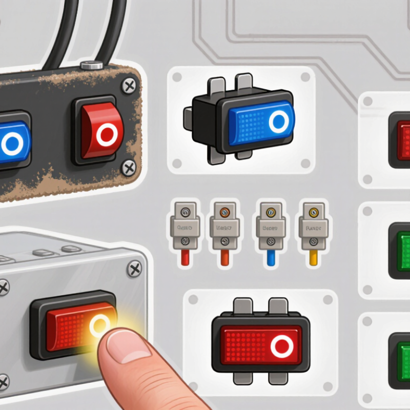
Table of Contents [Hide]
What Is an LED Rocker Switch and How Does It Work?
An LED rocker switch combines a mechanical rocker, electrical contacts, and a small light-emitting diode. Pressing the rocker changes the contact position. In a simple SPST version, one press connects the circuit, while another press breaks it. The LED then glows through a resistor, usually showing power or load status.
Its wiring is less obvious than it looks. A three-terminal model may use a common, supply, and output terminal. Some LEDs illuminate only when the load operates; others need a separate ground connection. Check the circuit diagram, not only the terminal shape. The required voltage matters too. A 12-volt switch should not be connected directly to a 24-volt system.
The IEA’s Energy Efficiency 2023 report estimates that lighting consumes about 15% of global electricity use. Efficient indicators can reduce small standby losses, but poor wiring still creates failures. IEC 61058-1 also emphasizes switch safety, insulation, and endurance requirements.
When choosing in 2026, compare current rating, AC or DC compatibility, panel cutout size, terminal protection, and operating temperature. A higher ampere rating is not automatically safer. Heat, vibration, and moisture can shorten service life. I once assumed a sealed rocker was waterproof; its rear terminals were not. Check the datasheet carefully.
Brands
Proudly Trusted by Top Suppliers Worldwide







Let us know and we will automate, together to fit your industrial needs.
 +91-97254 16844
Clients
Proudly Trusted by Top Companies Worldwide


Do you need Help? Get in touch.
X
Please fill out the form below and we will get back to you as soon as possible.