o
p
t
i
m
a
r
o
b
o
t
i
c
s

Make a Call


Make a Call
Blogs
How to Choose the Right Anchor Flange for Pipelines?
Choosing the right flange can determine whether a pipeline remains stable under pressure, temperature, and movement. In an Anchor Flange Pipeline, the flange does more than connect sections. It helps transfer axial loads into a concrete anchor block or structural support. Poor selection may cause leakage, bolt overstress, pipe displacement, or unexpected maintenance problems.
This guide explains how to evaluate flange size, pressure class, material, wall thickness, and connection type. It also considers soil conditions, thermal expansion, installation access, and the anchor block’s actual capacity. Experienced engineers compare operating data with approved drawings and applicable standards, such as ASME or project-specific specifications. Material compatibility matters, especially when water treatment chemicals, seawater, or aggressive fluids are involved.
A small mismatch matters.
Field experience shows that flange ratings alone do not guarantee a reliable installation. Bolting, gasket seating, weld quality, and alignment can be equally important. A flange may appear suitable in a catalogue but perform poorly when site conditions differ from design assumptions. That weakness deserves attention. Engineers should verify calculations, inspect delivered components, and confirm tolerances before installation. Independent review can also reveal overlooked loads or unclear responsibilities between the pipe designer and civil contractor.
The right choice is therefore not simply the strongest flange. It is the flange that matches the pipeline’s loads, environment, construction method, and long-term maintenance needs. Careful selection improves safety, service life, and confidence in the completed system.
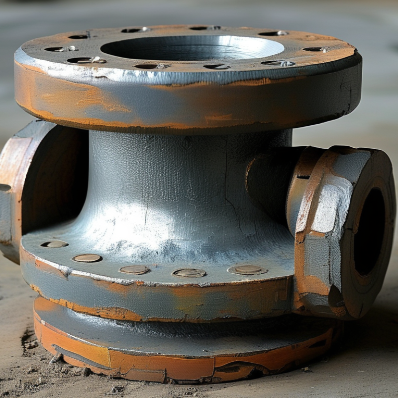
Table of Contents [Hide]
Define Anchor-Flange Function: Restrain Axial Loads, Pressure Thrust, and Moments
Choosing the right anchor flange begins with function, not flange diameter. An anchor flange creates a fixed point in the pipeline. It transfers axial loads into concrete, steelwork, or another stable structure. It also resists pressure thrust at bends, reducers, closed valves, and pipe ends. Moments can develop when the flow changes direction or supports settle unevenly. Load paths matter.
Specify design pressure, temperature, pipe material, test pressure, and expected movement before selection. Calculate pressure thrust from internal pressure and effective area. Do not rely on nominal pipe size alone. Check thermal expansion, surge, and installation tolerances. A flange that resists operating loads may still shift during hydrotesting. That detail is easy to miss. Confirm bolt-hole alignment, gasket seating, weld dimensions, and corrosion allowance.
The anchor block or structural frame must transfer forces into stable soil or steelwork. Reinforcement, embedment, and concrete bearing deserve the same attention as flange thickness. Verify bending and shear around the connection, especially near elbows and vertical risers. I have seen drawings that looked adequate until construction exposed soft backfill and a short support span. Engineering judgment needs site evidence. If data is uncertain, state assumptions and request review by a qualified pipeline engineer. “Fixed” is rarely absolute; small deflections can change load distribution.
How to Choose the Right Anchor Flange for Pipelines?
Define Anchor-Flange Function: Restrain Axial Loads, Pressure Thrust, and Moments
| Design Condition | Main Load to Restrain | Recommended Anchor-Flange Arrangement | Key Design Inputs | Selection Guidance | Required Verification |
|---|---|---|---|---|---|
| Straight pipeline section | Axial thermal movement and longitudinal pipe force | Anchor flange connected to a reinforced concrete thrust block, structural frame, or engineered pipe support | Pipe outside diameter, wall thickness, temperature range, coefficient of thermal expansion, restrained length, operating temperature | Use a flange with sufficient hub, weld, and bolt-section strength to transfer axial force into the surrounding structure. The support must be designed for the same load path. | Check axial stress, flange bending, weld capacity, bolt tension and shear, bearing, concrete breakout, and sliding resistance. |
| Change in direction | Pressure thrust caused by the change in momentum direction | Anchor flange located at or near the bend, tee, reducer, or capped end, with a load-bearing restraint system | Internal pressure, bend angle, pipe internal diameter, fluid density, flow velocity, fitting geometry | For a bend, evaluate the pressure-thrust vector and combine it with any weight, thermal, seismic, and hydraulic transient loads. Do not size the flange from pressure rating alone. | Check resultant force, local flange rotation, bolt-group forces, welds, thrust-block soil pressure, and foundation stability. |
| Closed end or blind termination | End-cap pressure thrust acting over the projected internal area | Anchor flange or restrained blind flange tied directly to a designed thrust-resisting structure | Design pressure, internal diameter, flange outside diameter, blind-flange thickness, bolt preload, gasket type | For a closed end, the pressure-thrust component can be estimated as F = p × A, where p is internal pressure and A is the projected internal area. | Check blind-flange bending, bolt preload and separation, gasket seating, pipe-wall stress, welds, and support reaction. |
| Reducer or diameter transition | Unbalanced pressure forces caused by different pipe areas | Anchor flange positioned where the reducer load can be transferred without overstressing the smaller pipe | Upstream and downstream diameters, pressure, reducer angle, flow direction, wall thickness, support spacing | Consider the pressure-force difference across the reducer together with dynamic and thermal effects. Confirm that adjacent flexible joints are not expected to carry the full thrust. | Check reducer stresses, flange load distribution, joint restraint, local buckling, and support reactions. |
| Valve, tee, or equipment connection | Combined axial force, pressure thrust, equipment nozzle loads, and local moments | Anchor flange paired with a rigid support or equipment base; use a flexible connection only where movement is intentionally permitted | Equipment allowable nozzle loads, valve mass, center of gravity, operating pressure, piping reactions, maintenance loads | Locate the anchor to control equipment loads while avoiding excessive restraint of thermal expansion. Coordinate the flange design with the equipment manufacturer’s allowable loads. | Check combined axial force, shear, torsion, bending moment, nozzle flexibility, bolt loads, and foundation stiffness. |
| Above-ground pipeline | Thermal expansion, wind, seismic action, vibration, and operating loads | Welded anchor flange with a guide-and-stop support arrangement designed to control movement in selected directions | Support span, pipe flexibility, temperature range, wind speed, seismic category, insulation weight, valve loads | Use anchors to define the piping flexibility system. Place guides and sliding supports so expansion is directed away from sensitive equipment. | Perform piping flexibility analysis and check support steel, anchor bolts, flange stresses, fatigue, vibration, and natural frequency. |
| Buried pipeline | Pressure thrust transferred through the pipe, anchor flange, thrust block, and surrounding soil | Anchor flange embedded in a properly reinforced thrust block or connected to an engineered restrained-joint system | Soil bearing capacity, friction angle, groundwater, burial depth, trench geometry, pipe diameter, pressure, fitting angle | Design the flange and thrust block as one system. Account for construction tolerances, drainage, soil variability, and possible loss of passive resistance. | Check bearing, sliding, overturning, uplift, reinforcement development, concrete shear, corrosion protection, and joint leakage. |
| High-pressure service | Pressure end load plus bolt preload, gasket reaction, and external restraint loads | Flange selected to the applicable pressure-temperature rating and designed for the actual external forces and moments | Design pressure and temperature, fluid service, flange material, bolt material, gasket factors, external moments | Select the pressure class or rating from the governing piping code and material group. A nominal rating does not replace a detailed flange-load assessment. | Check pressure-temperature rating, flange leakage, bolt stress, gasket compression, plastic collapse, fatigue, and corrosion allowance. |
| Combined load case | Axial force, shear, torsion, pressure thrust, and bending moment acting simultaneously | Anchor flange and support system sized for the governing factored load combination, not for one isolated load | Load combinations, operating and test pressure, temperature, seismic or wind loads, support stiffness, installation tolerances | Use the maximum credible operating, shutdown, hydrotest, surge, seismic, and maintenance cases. Apply the required code load factors and serviceability limits. | Verify interaction equations, flange rotation, bolt-group interaction, welds, pipe local stresses, support capacity, foundation response, and leak-tightness. |
Engineering note: An anchor flange is a load-transfer component, not only a pressure-rated connection. Final selection should be based on the governing piping code, design pressure and temperature, material compatibility, gasket and bolt requirements, restraint direction, and the capacity of the connected pipe and support structure.
Brands
Proudly Trusted by Top Suppliers Worldwide







Let us know and we will automate, together to fit your industrial needs.
 +91-97254 16844
Clients
Proudly Trusted by Top Companies Worldwide


Do you need Help? Get in touch.
X
Please fill out the form below and we will get back to you as soon as possible.