o
p
t
i
m
a
r
o
b
o
t
i
c
s

Make a Call


Make a Call
Blogs
What Are CNC Machine Parts and How Are They Used?
Cnc Machine Parts form the working anatomy of every computer numerical control system. They convert digital instructions into controlled cutting, drilling, turning, or milling movements. The spindle holds and rotates the tool. Bearings support smooth rotation. Guideways direct the machine table. Ball screws transfer motor power with measured precision. Servo motors provide movement, while the controller coordinates each axis. Small parts matter, too. A damaged seal can spread coolant. A worn bearing can leave visible lines on an aluminum surface.
CNC educator and author Mike Lynch has stated, “Accuracy begins with the machine’s mechanical condition.” This observation explains why operators inspect Cnc Machine Parts before blaming software or cutting data. A clean tool holder, correctly tensioned belt, and lubricated guideway can protect repeatability during long production runs. Yet the statement is not a complete rule. Temperature, material hardness, tool geometry, and operator judgment also influence results. That deserves attention.
This article examines what each major component does and where it fits inside the machine. It connects structure with practical use, from spindle assemblies to workholding devices and coolant systems. Readers will see why replacement parts must match the machine model, load, tolerance, and operating environment. A part may look interchangeable. It may not be.
Real workshops reveal the difference. Chips collect near covers. Vibration hides inside a loose coupling. Maintenance records often expose problems earlier than inspection alone. Understanding these details helps buyers, technicians, and machinists make safer, more reliable decisions. Mistakes still happen. Good knowledge reduces their cost.
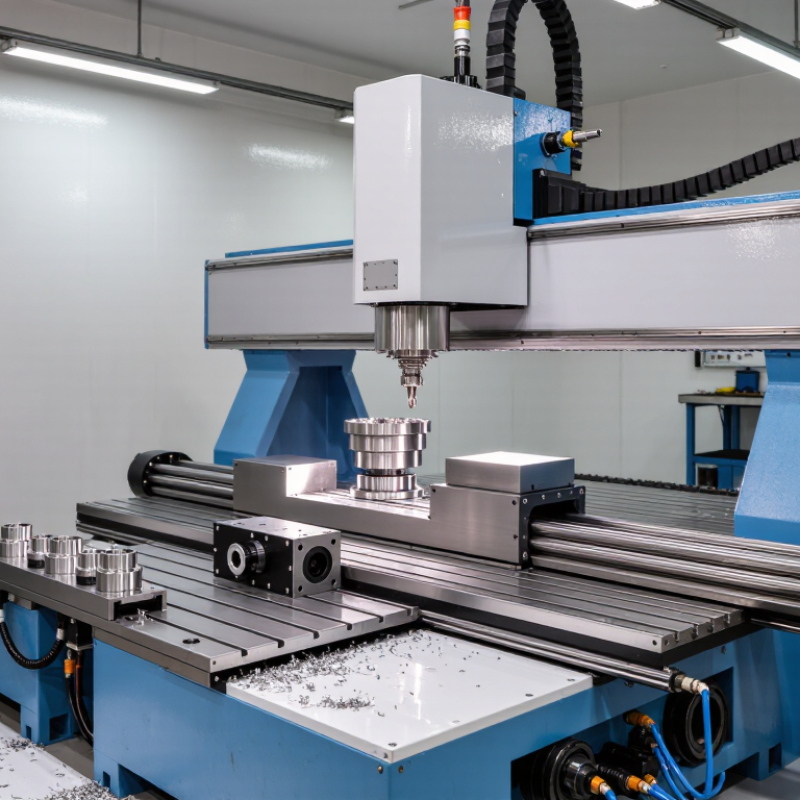
Table of Contents [Hide]
CNC Machine Architecture: Controllers, Frames, Spindles, and Drive Systems
What Are CNC Machine Parts and How Are They Used?
A CNC machine is an organized system of mechanical and electronic parts. The controller reads programmed coordinates and converts them into electrical commands. It manages motion, speed, tool changes, and emergency stops. Accuracy begins with the frame. A heavy, well-aligned frame resists vibration during cutting. Linear guides support smooth movement along each axis. Ball screws then transfer motor rotation into controlled table or spindle movement.
The spindle holds and rotates the cutting tool. Its bearings must remain stable under heat and cutting pressure. A powerful spindle is not always better. The correct speed depends on the material, tool diameter, and cutting depth. Drive systems include motors, couplings, screws, belts, and feedback devices. These parts determine acceleration, positioning accuracy, and surface finish. In practice, a small alignment error can leave visible lines on a metal surface.
Tips:
- Check frame alignment before blaming the controller.
- Listen for unusual spindle noise.
- Keep guides clean and lubricated.
- Measure backlash regularly.
- Do not ignore heat buildup. It changes dimensions.
The controller and drive system must work as one unit. Feedback sensors report actual position, allowing corrections during movement. Without reliable feedback, commanded accuracy may remain only an assumption. I have found that maintenance records often reveal problems earlier than inspection alone. Still, no setup is perfect. Tool wear, temperature changes, and operator habits can affect results. A careful technician checks the machine under real cutting conditions, not only during an idle test.
Brands
Proudly Trusted by Top Suppliers Worldwide







Let us know and we will automate, together to fit your industrial needs.
 +91-97254 16844
Clients
Proudly Trusted by Top Companies Worldwide


Do you need Help? Get in touch.
X
Please fill out the form below and we will get back to you as soon as possible.