o
p
t
i
m
a
r
o
b
o
t
i
c
s

Make a Call


Make a Call
Blogs
What Is Spray Can Machinery and How Does It Work?
Spray Can Machinery is the production system behind the familiar metal cans found in homes, workshops, and retail stores. It transforms flat metal sheets into strong, precise containers. The process usually includes sheet feeding, cup forming, body shaping, trimming, washing, printing, and quality inspection. Each stage controls a visible detail, such as wall thickness, rim accuracy, or print alignment.
Aerosol-packaging engineer John D. Lewis explains, “Reliable cans begin with controlled forming, not final inspection.” This principle describes the entire manufacturing line. Machines must coordinate speed, pressure, tooling, lubrication, and temperature. Small errors can create dents, weak seams, or uneven dimensions. These defects may appear minor. They are not.
Modern Spray Can Machinery also supports automated testing. Cameras inspect surfaces. Sensors monitor measurements. Pressure and leak checks help confirm container integrity. Proper guarding and maintenance protect workers and equipment. Production lines must also follow applicable packaging, workplace safety, and environmental requirements. Standards differ between markets, so responsible manufacturers verify current rules before operation.
The technology is highly engineered, but it is not flawless. Tool wear, material variation, and incorrect settings can still affect results. Experienced operators remain important. They notice unusual vibration, sound, or surface marks before a larger problem develops. A well-designed line therefore combines automation with human judgment. This article examines how Spray Can Machinery works, why each stage matters, and where real-world production can become difficult.
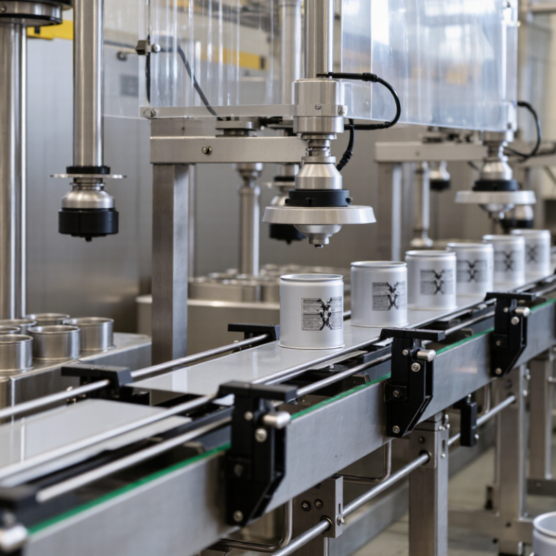
Table of Contents [Hide]
Definition and Main Types of Spray Can Machinery
Spray can machinery is a group of industrial systems used to produce, fill, seal, test, and pack aerosol cans. It does not describe one machine. Instead, it is a connected production line. Empty metal bodies move through guided conveyors while sensors check their position. Valves, products, and propellants are added in controlled stages. Pressure and cleanliness must remain consistent.
The main types include can-making machinery, filling machinery, crimping machinery, testing equipment, and packaging systems. Can-making machines shape aluminum or tinplate into cylindrical bodies. Filling machines measure the product accurately before inserting the valve. Crimping machines press the valve onto the can neck, creating a tight seal. Leak-testing units may use pressure checks, water baths, or electronic sensors. Labeling and case-packing machines prepare finished cans for storage and shipment.
Each system has a different responsibility. Together, they control speed, accuracy, and worker safety. Modern lines often include automatic inspection cameras and programmable controls. These tools can detect dents, missing valves, or incorrect labels within seconds. However, automation is not perfect. Dust, worn seals, or poor calibration can still cause failures. Experienced operators inspect samples, record pressure readings, and adjust settings carefully. The process also depends on local safety standards, approved materials, and proper ventilation. Small details matter. A slightly damaged rim may affect sealing, while an inaccurate fill can change spray performance. In practice, reliable machinery requires both precise engineering and regular human judgment.
Brands
Proudly Trusted by Top Suppliers Worldwide







Let us know and we will automate, together to fit your industrial needs.
 +91-97254 16844
Clients
Proudly Trusted by Top Companies Worldwide


Do you need Help? Get in touch.
X
Please fill out the form below and we will get back to you as soon as possible.