o
p
t
i
m
a
r
o
b
o
t
i
c
s

Make a Call


Make a Call
Blogs
What Are the Top Types of Electrical Testing for PCBs?
Printed circuit boards rarely fail in dramatic ways. A microscopic copper break, a solder bridge, or a weak plated-through hole can quietly interrupt a signal. Electrical Testing Pcb methods help uncover these defects before boards reach assembly or service. The need is growing with the market: Grand View Research’s Printed Circuit Board Market Size, Share & Trends Analysis Report estimated the global PCB market at USD 76.2 billion in 2023. More production means more value in verifying every connection.
The main methods answer different questions. Continuity and isolation tests check whether intended paths conduct and unwanted paths remain separate. A bed-of-nails fixture tests many points quickly, making it useful for repeat production. Flying-probe testing uses movable probes and avoids a dedicated fixture, which can suit prototypes and low-volume runs. Boundary-scan testing checks access through compatible chips, while functional testing evaluates a board’s behavior under defined operating conditions. Each method has limits. No test catches everything.
IPC-9252B, Requirements for Electrical Testing of Unpopulated Printed Boards, provides industry guidance for bare-board testing. IPC’s 2023 North American PCB Production report adds manufacturing context, where product mix and production scale shape inspection choices. In practice, engineers often combine methods: a flying probe for early revisions, then fixture-based testing as volume rises. The right choice depends on access, pitch, cost, and risk—not a single “best” machine. Test plans also need review; a clean pass can still miss faults outside the test’s coverage.
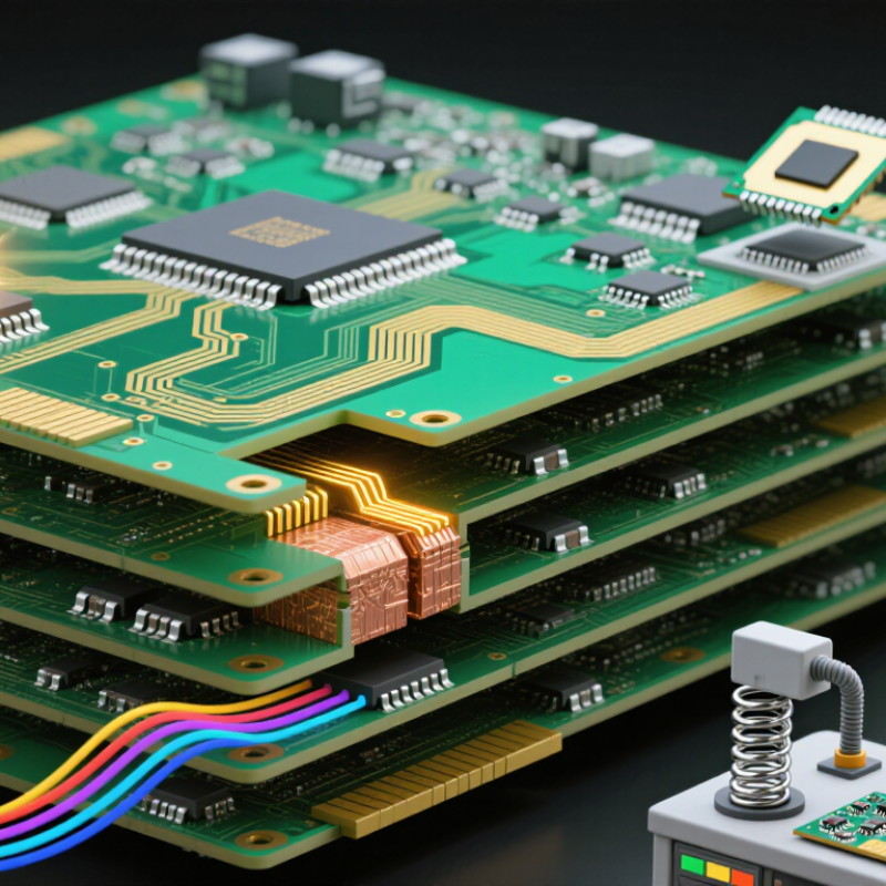
Table of Contents [Hide]
Continuity and Short-Circuit Testing for PCB Connections
Continuity testing checks whether each intended PCB path remains electrically connected from pad to pad, via to via, or connector to component. A flying-probe tester touches exposed points and compares measured resistance with the board’s specified limits. IPC-9252B, the industry specification for electrical testing of unpopulated printed boards, addresses continuity and isolation checks. Limits should match the design: a long, narrow copper trace will not read like a short, wide power plane. Small differences matter.
Short-circuit testing looks for unintended connections between separate nets, often caused by solder bridges, copper slivers, or damaged insulation. Test software compares the measured netlist against the board’s design data, then flags unexpected low-resistance paths. For example, an engineer might check all 800 nets on a sample board and investigate any unexpected connection between adjacent fine-pitch pads. That figure is illustrative, not an industry-wide benchmark. IPC-6012 provides additional performance and qualification requirements for rigid boards, while the actual acceptance thresholds depend on the drawing and customer specification. Keep the fixture clean, confirm probe contact, and retest suspicious readings; a little contamination can imitate a fault. I have seen teams trust one test pass too quickly. That can be a costly assumption.
Brands
Proudly Trusted by Top Suppliers Worldwide







Let us know and we will automate, together to fit your industrial needs.
 +91-97254 16844
Clients
Proudly Trusted by Top Companies Worldwide


Do you need Help? Get in touch.
X
Please fill out the form below and we will get back to you as soon as possible.