o
p
t
i
m
a
r
o
b
o
t
i
c
s

Make a Call


Make a Call
Blogs
How to Choose a Collaborative Robot Arm in 2026?
Choosing a collaborative robot arm in 2026 requires more than comparing payload and price. The right model must fit the real workstation, not just the product brochure. Imagine a technician lifting a 12-kilogram fixture beside the robot. Reach, mounting position, cycle time, and human access suddenly become practical concerns. A compact arm may improve access, while a heavier model may offer better stability. Neither option wins automatically.
Esben Østergaard, a co-founder of Universal Robots and a recognized collaborative robotics expert, has said, “Cobots are not designed to replace people, but to work alongside them.” That principle should guide every buying decision. Review payload, reach, repeatability, end-effector compatibility, programming effort, and integration support. Examine force limits, safety functions, and risk assessment requirements against applicable standards and local rules. Ask suppliers for realistic cycle-time tests. Request references from facilities with similar materials, shifts, and production pressures.
The cheapest arm may create expensive downtime. The most advanced arm may overwhelm a small team. That assumption can fail. Operators need clear interfaces, simple recovery steps, and practical training. Maintenance staff need accessible cables, documented diagnostics, and available spare parts. Total cost includes installation, tooling, software, training, energy, and future changes.
No checklist is perfect. Your process may change next year. Therefore, select a collaborative robot arm with measurable performance, credible technical support, and enough flexibility for uncertain work. The following guide examines these factors closely, helping readers compare options with evidence rather than impressive demonstrations alone.
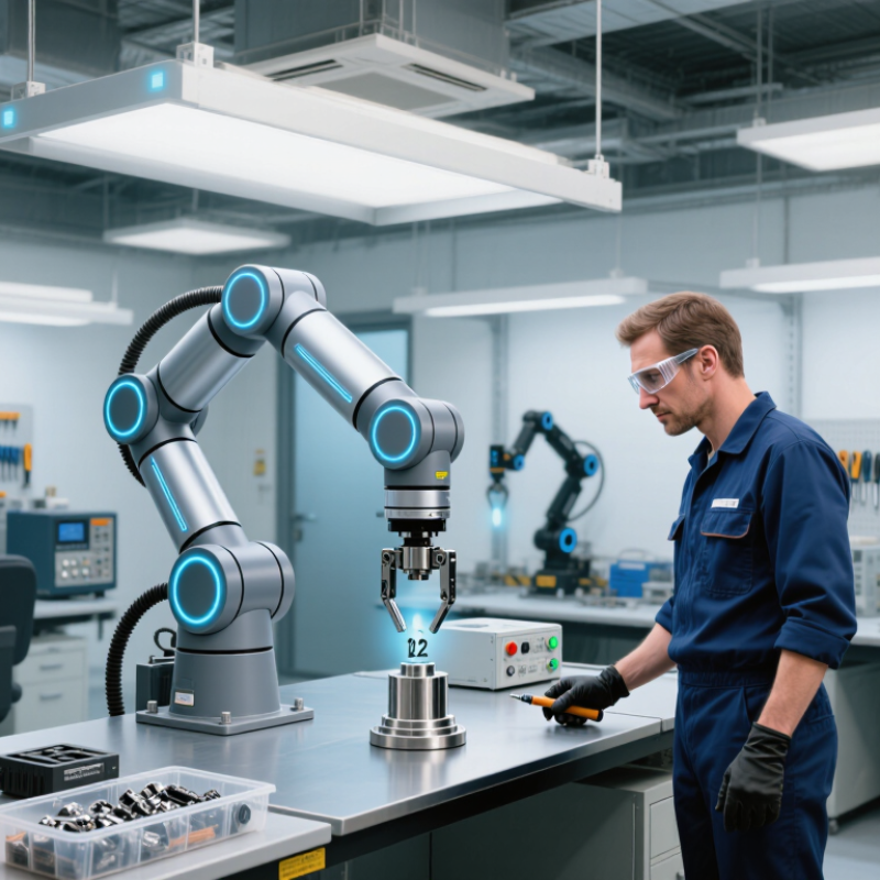
Table of Contents
[Hide]
Define the Tasks and Work Environment
How to Choose a Collaborative Robot Arm in 2026?
Define the task before comparing robot arms. Record payload, reach, cycle time, accuracy, and tool weight. A 6-kilogram part may require a heavier arm after adding the gripper and safety margin. Measure the real workflow for several shifts. One ideal cycle can hide awkward loading, operator pauses, and changing part sizes. The International Federation of Robotics reported 542,000 industrial robot installations worldwide in 2023, a 10% annual increase. This growth reflects practical automation demand, not a reason to automate every station.
Study the work environment closely. Is the floor dusty, humid, refrigerated, or exposed to cleaning chemicals? Check the required ingress protection, operating temperature, lighting, and available floor space. A narrow aisle may favor a compact arm, while a high shelf needs greater reach and stable mounting. Human contact also matters. Collaborative operation depends on risk assessment, reduced speed, force limits, and suitable tooling. ISO 10218 and ISO/TS 15066 provide useful safety frameworks, but compliance cannot be assumed from a product label.
Test the complete task.
Use the actual fixture and parts. Observe pinch points, cable movement, and handover timing. The arm may pass a demonstration yet fail beside a vibrating conveyor. That is an uncomfortable lesson. Leave capacity for future payload changes, but avoid buying unnecessary reach. The IFR World Robotics 2024 report recorded a global robot density of 162 units per 10,000 manufacturing employees in 2023, showing how quickly deployment is expanding. Selection should remain evidence-based, documented, and reviewable by qualified safety personnel.
How to Choose a Collaborative Robot Arm in 2026? - Define the Tasks and Work Environment
Use the task profile, required payload, reach, accuracy, operating conditions, and safety needs to create a practical initial specification before comparing robot systems.
| Typical Task | Typical Payload Requirement | Recommended Working Reach | Typical Position Repeatability | Recommended Degrees of Freedom | Typical Operating Speed | Work Environment | End-Effector and Integration Needs | Key Safety Considerations | Selection Priority |
|---|---|---|---|---|---|---|---|---|---|
| Machine tending | 5–16 kg, including the gripper and workpiece | 800–1,500 mm | ±0.03–0.10 mm | 6 or 7 axes for access around machine doors and fixtures | Moderate; cycle time commonly depends on machine loading and unloading | Metalworking areas may contain coolant, chips, oil mist, and variable temperatures | Part-present sensing, machine I/O, door interlocks, and a gripper matched to part geometry | Risk assessment for pinch points, sharp parts, automatic machine start, and stored energy | Payload margin, reach, ingress protection, machine communication, and cycle time |
| Packaging and case packing | 3–12 kg | 900–1,600 mm | ±0.05–0.15 mm | 6 axes; an additional external axis may be useful for long conveyor layouts | Moderate to high; speed must be validated with the actual payload and motion profile | Usually clean and organized, with conveyors, cartons, film, labels, and changing product sizes | Vacuum or mechanical gripper, conveyor tracking, barcode or vision inspection, and recipe management | Assess access to conveyors, carton edges, dropped products, and unexpected restart conditions | Reach, throughput, gripper flexibility, conveyor synchronization, and changeover time |
| Palletizing and depalletizing | 8–25 kg, depending on the case, layer pattern, and tooling | 1,200–2,000 mm | ±0.05–0.20 mm | 6 axes; layout and pallet height may require a seventh axis or lift mechanism | Moderate; acceleration and deceleration affect load stability | Warehouse or production-floor conditions with pallets, forklifts, dust, and variable traffic | High-capacity gripper, pallet detection, layer pattern software, and pallet conveyor integration | Separate pedestrian and forklift routes; evaluate dropped-load, collision, and pallet-access risks | Payload, reach at maximum pallet height, stability, floor space, and safeguarding strategy |
| Pick-and-place assembly | 0.5–8 kg | 600–1,300 mm | ±0.02–0.08 mm | 6 axes for flexible orientation; 4 or 5 axes may suit planar applications | Moderate to high, provided the parts and fixtures tolerate the motion | Clean, organized workstation with fixtures, feeders, conveyors, and operator interaction | Part-present sensors, force or torque sensing for insertion, vision, and flexible feeding | Check hand-clearance zones, insertion forces, sharp components, and collaborative contact limits | Repeatability, force control, vision compatibility, cycle time, and ease of programming |
| Screwdriving and fastening | 2–10 kg, including the fastening tool | 600–1,200 mm | ±0.02–0.08 mm | 6 axes for multi-angle access and tool orientation | Moderate; fastening time is often governed by torque, screw feed, and verification | Assembly area with small parts, feeders, tooling, and possible airborne dust or oil | Electric screwdriver, automatic screw feeder, torque monitoring, depth verification, and tool changer | Control tool reaction torque, bit hazards, dropped screws, unexpected tool rotation, and restart behavior | Tool payload, positional accuracy, torque integration, access angle, and process verification |
| Dispensing, gluing, and sealing | 2–12 kg, including material cartridges, hoses, and applicator | 700–1,400 mm | ±0.03–0.10 mm | 6 axes for continuous path control around curved components | Low to moderate; stable path velocity is usually more important than peak speed | May include chemical exposure, fumes, temperature variation, and contamination-control requirements | Metering pump, pressure regulation, bead inspection, hose management, and material-level monitoring | Review chemical compatibility, ventilation, leakage, hose snagging, and emergency-stop behavior | Path accuracy, velocity stability, payload, material compatibility, and cleaning requirements |
| Inspection and quality checking | 1–8 kg, often dominated by camera, lighting, or sensor weight | 600–1,500 mm | ±0.02–0.10 mm | 6 axes for viewing from multiple angles; fewer axes may suit fixed inspection paths | Moderate; image quality and exposure time can determine throughput | Controlled lighting is important; dust, vibration, reflections, and temperature can affect results | 2D or 3D vision, lighting, measurement software, reject handling, and traceability systems | Protect lenses and cables; assess motion near operators, fixtures, and rejected parts | Repeatability, vibration control, sensor integration, lighting consistency, and data connectivity |
| Welding and light fabrication | 5–15 kg, including torch, cable package, and workpiece | 900–1,500 mm | ±0.03–0.10 mm | 6 or 7 axes for torch orientation and access to complex joints | Moderate; path stability and process parameters are critical | Heat, sparks, fumes, arc radiation, electromagnetic interference, and metal debris may be present | Welding power source, torch cleaning, seam tracking, fume extraction, and cable management | Usually requires dedicated guarding or controlled access; apply welding, fire, fume, and electrical controls | Environmental protection, cable routing, path accuracy, process integration, and safeguarding |
| Laboratory and clean-area handling | 0.5–6 kg | 500–1,200 mm | ±0.02–0.08 mm | 6 axes for flexible handling of vessels, trays, and instruments | Low to moderate; gentle motion can be more important than maximum speed | Cleanroom, controlled laboratory, or temperature-sensitive environment | Low-particle materials, smooth surfaces, washable tooling, sterile or sealed grippers, and traceability | Assess contamination, fluid spills, biological or chemical hazards, and restricted-access procedures | Cleanability, material compatibility, repeatability, quiet operation, and data logging |
| Human-shared workstation | 1–8 kg, with a conservative margin for dynamic loads | 600–1,300 mm | ±0.03–0.10 mm | 6 axes for flexible positioning around the operator and fixture | Limited by the validated collaborative operating mode, tool, payload, and risk assessment | Open workstation with frequent operator access and changing task conditions | Force or torque sensing, compliant gripper, clear status indication, ergonomic fixtures, and quick restart | Complete a documented risk assessment; consider speed, force, sharp edges, trapping zones, and predictable stopping | Safety functions, ease of deployment, ergonomics, risk-reduction measures, and operator acceptance |
Values are practical planning ranges rather than universal limits. Final selection should be validated using the complete tool, workpiece, motion profile, fixture, environmental conditions, and a documented risk assessment in accordance with applicable machinery-safety requirements, including ISO 10218 and ISO/TS 15066 where relevant.
Related Posts
-

Unlocking Creativity: How a Small Robotic Arm Can Transform Your DIY Projects
-

What is a small robotic arm and how does it work?
-

2026 Best Cobot Robot for Efficient Manufacturing Solutions?
-
2026 Best Robotics Stocks to Buy Worldwide?
-

What Is a Universal Robot Arm and How Does It Work?
-
How to Choose the Right Robotics and Automation System
Brands
Proudly Trusted by Top Suppliers Worldwide







Let us know and we will automate, together to fit your industrial needs.
 +91-97254 16844
Clients
Proudly Trusted by Top Companies Worldwide


Do you need Help? Get in touch.
X
Please fill out the form below and we will get back to you as soon as possible.